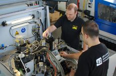

Schwer + Kopka GmbH
Your system specialist for Industry 4.0 projects in high volume mass production.
mehr Infos


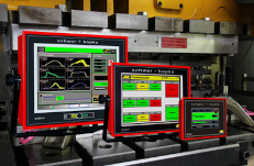
SK-go! EMS
Efficient management of energy consumption and production data for mass producers.
mehr Infos

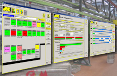
OEE factors
Automatically collected, objective and non-manipulable - straight to your desk.
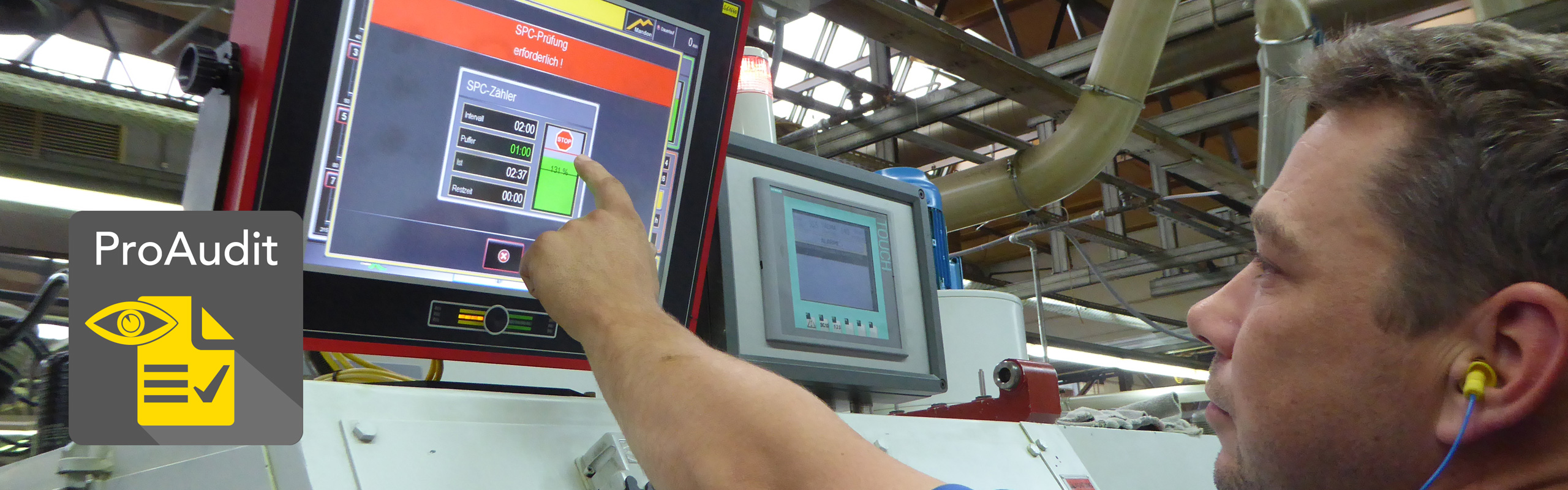
SK-go! ProAudit
Make your auditor happy: 7 steps towards a stable and controlled production process with full proof of compliance.
mehr Infos

Definitions
Various keywords and terms are regularly used in the topics of process monitoring, tool protection, machine protection and sensor technology. Here you will find explanatory information and definitions on a number of points from the perspective of our daily practice:
Punching tools are often tested by special sensor scannings to find out whether the finished stamped parts have actually left the tool after the working stroke. Here mostly inductive sensors are used in flat or annular form, which are mounted in the ejection zone of the tools and switch in the presence of metal. If the stamped part passes the sensor in the specified crank angle range, the sensor switches and signals "ok". If the signal fails, the last stamped part is probably still in the tool and can do considerable damage during the following stroke. The machine must now be stopped immediately and the cause of the error must be eliminated.
Modern monitoring systems offer different query models for ejection control in order to be able to react appropriately to all peculiarities of the part ejection. In some tools, the finished stamped parts are still in an ejection chute and fall rather irregular from the tool. In this case, for example, the query can be set so that at least every 3 strokes one or more parts must have passed the ejection sensor.
Rising slugs or stamping scrap are an ubiquitous problem in the production of stamped parts. It may happen, for example, that after the piercing the slug sticks to the punch during withdrawal and falls onto the strip at the next stroke where it leaves a mark on the surface. Such parts are usually scrap! Unfortunately, this error occurs only sporadically, so it is hardly found during the usual random checks.
The detection of rising slugs or scrap is possible with intelligently placed force sensors. Ideally, one or more piezo-electric sensors are mounted at appropriate locations on the so called stripper or guide plate. The process monitoring system memorizes in a learn procedure, how the stripper plate presses down the shett metal strip during the working stroke and creates a matching envelope around the associated force curves. If slug is pulled up and drops onto the strip in a working stroke, the stripper plate is disturbed in its usual movement. The measured forces change, the machine stops and the operator can remove the faulty parts.
Batching or dosing devices are used to successively fill the produced parts at the exit of the machine into several component containers. In the most common types, the containers are arranged on a rotating carousel or in-line. If one container is filled, the next container is automatically moved under the machine exit chute.
To control the devices, process monitoring systems have the so-called batching counter, in which the capacity per container and the number of available containers are specified. When a partial quantity is reached, a relay switches and moves the batching device to the next filling position. If all component containers are filled, the machine is switched off.
These are the advantages of using dosing devices:
- higher storage volume for longer, undisturbed running times
- machine operator is relieved of frequent routine work (emptying of containers)
- increases runtime potential in unmanned shifts
- reduced scrap quantity (only partial quantities have to be scrapped if errors occur)
Reproducibility of the tool and machine settings is an essential factor for repeatable and reliable production! Auditors also regularly check whether the company has guidelines and specifications for setting the machine and tools for the individual parts as also outlined in IATF 16949.
The following procedure offers a simple and pragmatic setup help:
If a part is running perfectly, all monitoring parameters and the current force curves are stored in the process monitoring system under the part or tool number. The next time the same part is produced again, the stored target data is reloaded and all monitoring parameters are automatically set to the saved good values. Now the current force curves can be compared with the stored tested and approved nominal curves on the screen of the monitoring device. It can be seen directly whether and where deviations exist and in which direction the tool and machine settings must be corrected if necessary.
Envelope monitoring has established itself as the standard technology for effective and sensitive monitoring of production processes in series production. In a learn procedure, the monitoring systems automatically record the typical signal sequences, e.g. from force sensors, and store them as target curves for the currently running parts. The curve of each subsequently manufactured part is compared with the learned target curve. The so-called envelopes are used as limits, which are automatically set by the monitoring system around the scatter range of the signal paths. The width of the envelopes can be automatically set to achieve the best possible fit to the process variation and thus the best possible monitoring results.
It is also possible to move the limits manually. Impermissible deviations lead to an immediate shutdown of the machine in order to avoid further defective parts, and to protect machine and tool against overload. Alternatively, in the case of envelope violations, the affected error parts can be rejected by sorting gates, which are automatically controlled by the monitoring system. Sophisticated algorithms ensure that even minor errors are detected reliably, while avoiding unnecessary machine shutdowns as far as possible.
Typical manufacturing errors often become noticeable by identical or very similar changes in the measurement signals. If the changes in the signal curves to be monitored for certain errors are known, these can be stored as a sample in the software. The process monitoring system responds immediately when it recognizes the pattern again, and notifies the machine operator of the detected error type. The special advantage of stored sample curves is that the recognition works independently of the set envelopes. This can reliably detect the errors even in case of coarse envelope settings.
Piezoelectric sensors have established themselves as standard for the monitoring of series production processes. They are used to measure the loads and forces that are present in the machine and the tools during production. The sensors are usually placed firmly in the machine or tool parts that absorb the machining forces. Through skillful placement, they can be used both for the measurement of very small forces as well as high loads. Piezo sensors are available in various mechanical versions for gluing, cementing, inserting, bolt on/in, dowel-shaped, etc..
Piezo measuring devices generate a so-called electrical charge when they are pressed, bent or deformed in any way. The generated signals are converted by means of charge amplifiers into voltage signals, which are further processed in the evaluation electronics. They directly map the work process, e.g. in the form of a press force curve, and provide the basic information for process monitoring.
Piezo sensors are very well suited for cyclic processes in series production with correspondingly high cycle rates. For very slow or static processes they are not suitable, but are replaced by sensors based on strain gauge technology.
Machines for the forming technology must be able to provide the high forces required for the production of the formed parts. All machines, especially presses, are designed for a certain maximum load, which should not be exceeded in practice, as otherwise permanent damage could occur. Therefore, most presses are equipped with a press force monitoring system that measures the current forming forces and monitors them with limit values while the system is running.
The forces are usually measured by means of so-called strain gauges, which are attached to the frame or the machine body. They detect how the machine body stretches or elongates under the pressing load. In a calibration process, the elongation of the machines is converted into the actual pressing force in kilo Newtons (kN).
Specified limits ensure that the maximum loads for the respective machines are not exceeded.
Producing in so-called blind or unmanned shifts means that the machines work without human supervision. This cost-saving production method became possible only with the development of process monitoring systems. With the help of the process monitors, the machine running time could be decoupled from the attendance time of the personnel. The machines keep running after the end of the regular shifts or over the weekend until either, in the event of a fault, the machine is shut down by the process monitor, the material stock is used up or the storage capacity for finished parts is exhausted.
Whether a blind shift is actually feasible, does of course depend on whether the production process offers enough capacity for unmanned production, for example, in terms of lot sizes, the achievable tool life or the available material supply. The term blind shift is also used when machines continue running during breaks and shift changes, times in which they are usually switched off without installed process monitoring. Some companies leave a time buffer between 2 shifts and bridge it with a short blind shift.
In some industries, production in blind shifts is common practice and ensures that many alleged cheap products can still be produced economically in high-priced industrialized countries.
Reducing production scrap is one of the main tasks of process monitoring. In the event of malfunctions such as tool breakage, material defects, feeding and handling faults, the production machine is switched off immediately in order to avoid further defective parts and to protect the machine and tool from consequential overload damage. Without the use of process monitoring, larger production quantities often have to be scrapped, as even a few sporadic missing parts may have contaminated the existing yield, and in many cases a separation is technically or economically impossible.
Process monitoring is particularly effective with suitable sorting gates, which are activated by the monitoring system when faults occur and automatically separate the error parts without stopping the machine. Contamination of the existing yield is thus avoided while the productivity of the machines is significantly improved.
Today's serial production machines are often equipped with state-of-the-art process monitoring systems that ensure controlled and reliable production. The production is mostly controlled by measuring the manufacturing forces and monitoring them by means of dynamic envelope technology with immediate stop of the machine in case of hurting envelope limits. Any detected or supposed errors, as well as random fluctuations in the sensor signals, lead to a more or less long machine downtime, which impairs the productivity of the system. Operators often tend to unnecessarily coarse envelope limits just for a bit of “peace”. As a result, of course, the reject rate rises again due to wasted monitoring accuracy.
Therefore, an automatic sorting of error and "suspicious" parts with appropriate sorting flaps makes sense while the machine continues to run. Detected errors are safely rejected and cannot mix with the previously produced good parts. Envelopes stay enough fine-adjusted without unnecessary machine stops. The machine is only switched off when multiple errors occur in succession.
Modern process monitoring systems offer a variety of settings for a machine-adapted control of the sorting gate including a function check by monitoring limit switches on the gate.
Wrong or not optimally adjusted dies for thread rolling are one of the main causes of poor thread quality and rapid tool wear! Only experienced machine setters achieve perfect results when setting the tools. Die match errors arise when the two thread rolling dies are not correctly adjusted to each other. Only with precisely adjusted rolling dies, the thread profiles rolled by the two halves of the die set run cleanly into one another. If the tool setting is bad, the thread profile formed by one rolling die is displaced slightly laterally from the other die. These alignment errors (thread laps) weaken the thread and are therefore not allowed. In addition, the lateral load on the thread profile of the dies increases and can reduce the lifetime drastically.
In a monitoring system with automatic die match indicators (DMI), sensors and a tailored software make immediately visible whether the position of the two dies is correct, or whether an adjustment is required. The measurement takes place at full production speed and thus maps the real conditions of production. Often only minimal fine corrections of the die match position are necessary to achieve maximum operating life, which can hardly be achieved with dexterity.
We have field-tested solutions for all common and suitable rolling machines from various manufacturers.
Punches in forming or stamping tools are used to shape a certain contour into the material to be processed, to punch a hole, to make an embossing, to extrude the material or to bend it. The contours generated are usually functionally relevant, so that punch breakage or breakouts always lead to defective parts, which must be detected as soon as possible during production.
With intelligently placed sensors, e.g. for press force or acoustic emission, many punch breakages can be detected directly on the first occurrence.
Manufacturing processes do not only change suddenly as in the case of tool breakage, but also gradually due to wear effects, machine malfunctions that occur over time, changes in material strength or lubrication conditions. This does not always lead to defective parts, but one should keep an eye on the development.
Trend monitoring measures and controls how the process signals change over time and whether limits are exceeded. Easily adjustable upper and lower trend limits ensure that the process cannot move away more than allowed from the start level.
Modern process monitoring systems use trend monitoring and display the measurement results in a clear graphic. Trend monitoring limits a possible drift and secures the production process against unwanted "wandering away".
Production machines, in particular presses, are designed for certain maximum loads. If these limits are exceeded, there is a risk of overload damage to various machine components. In extreme cases, the machine can even be destroyed.
For overload protection, usually so-called strain sensors are mounted on the machine body, which register the elongation of the machine body under operation pressure. Reference sensors are used to calibrate the measuring chains in the machine to give force readings in true kilo Newtons (kN), Adjustable limits ensure that the machine and, of course, the built-in tools are protected against overload.
Overload protection is available in modern process monitoring systems as a supplement to the monitoring of the individual tool stages. The machine load and the set limit values are displayed on an easy-to-read graph. On request, any overloads that have occurred can be logged in the system.
One of the most important functions when punching from coil is the correct feed of the strip of material between 2 working strokes. If the strip is not fed forward enough, the parts punched at the following stroke are usually scrap. Especially with high-speed machines, the available time for the feed is tight; the feed must be ready before the tool closes again. Therefore, in most punching tools, sensors such as photoelectric barriers or inductors are mounted in the proper locations to check that the strip has been forwarded sufficiently. The query may, for example, be done at the front cutting edge of the strip or at an inserted reference edge in the strip. Decisive for the test accuracy is that the position of the sensor is set as accurately as possible to the sensing edge. For extremely precise feed controls, analog light barriers are availalbe, which provide an analog, proportional measurement signal depending on the degree of coverage of the light beam.
The processing of binary sensors and a convenient operation and setting of queries and query times via touch-screen are part of modern punching monitoring systems.
In the punching technique, the term "tool protection" refers to the query of important functions in the punching tool by means of binary sensors. Such sensors are, for example, photoelectric barriers, which check whether the punching strip has a hole at a certain place. If this is the case, the photoelectric barrier can pass and indicates "ok". If the hole is missing, perhaps because the stamp has broken, the signal query goes to malfunction and stops the machine. Photoelectric barriers can also be used for feed control. In this case, a query is made at a suitable location to make sure that the strip of material was also forwarded before the start of the next stroke..
Other typical sensors are initiators or proximity sensors that react to the presence of metal. They are used, for example, to query whether the finished punched parts have left the tool after the working stroke of the press (ejection control). If this is not the case, the parts are still in the tool and can cause major damage at the next stroke. Therefore, the machine must be stopped immediately..
Modern monitoring systems offer extensive query variants for the various controls and sensor types, which can be easily and simply set via touch screens.